Inspiration

Smart TFT LCD Display: A Practical Guide from Selection to Development Deployment

2026-07-29 0 Leave me a message

In embedded system and human-machine interaction design, the Smart TFT LCD Display is no longer merely a "display component" — it is a critical factor that determines user experience and product success. Whether you are developing an industrial HMI, a smart home control panel, or a handheld medical device, navigating the vast array of Smart TFT LCDs on the market and making the right choice while ensuring rapid deployment is often more complex than it seems.


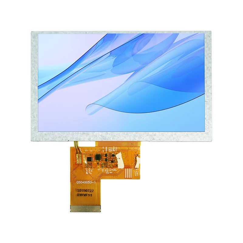
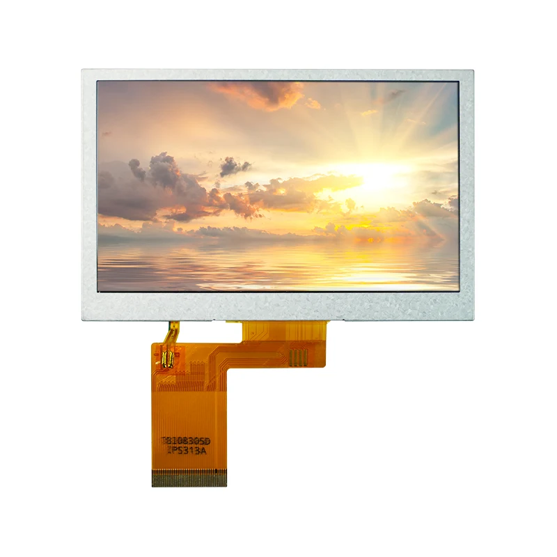
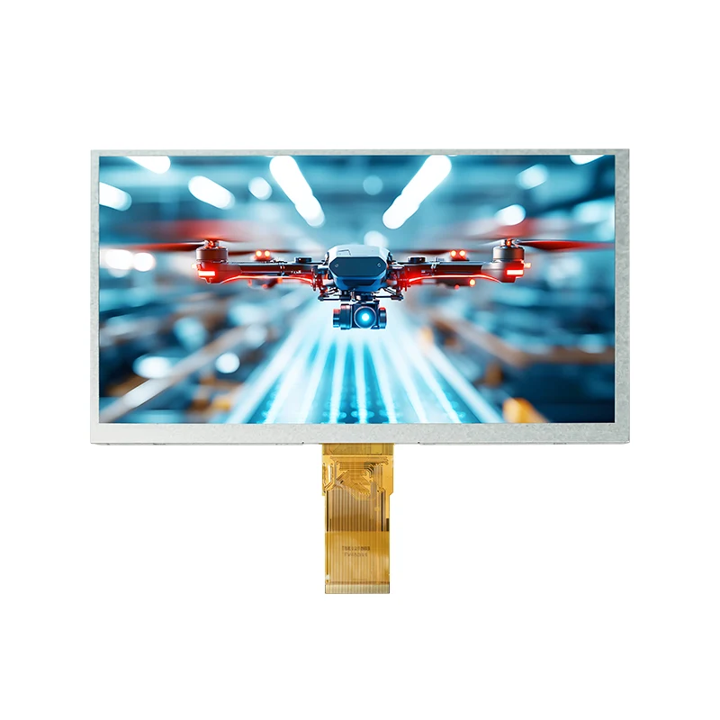
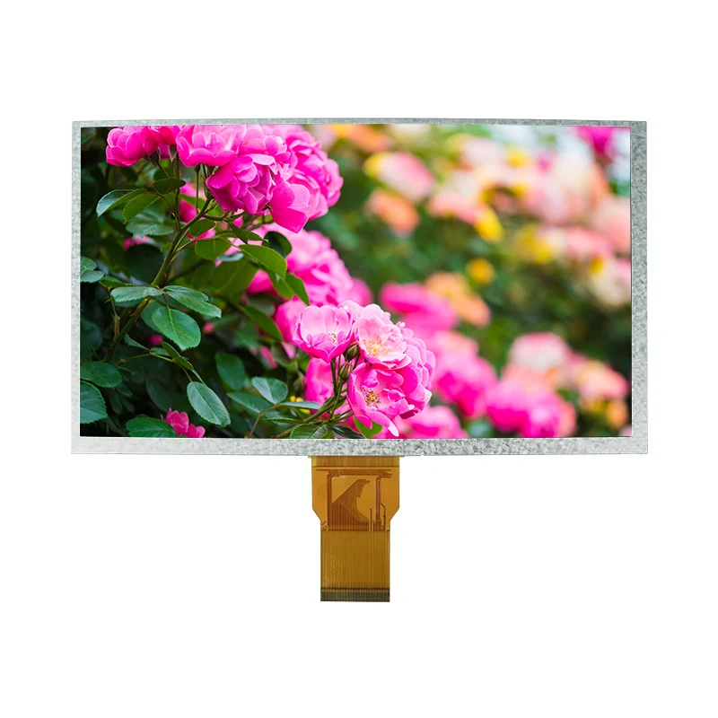
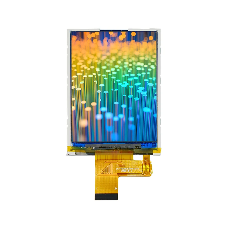
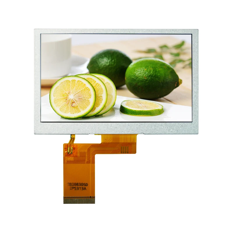
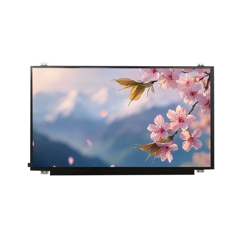
Smart TFT LCD Display

1. Selection: Don't Just Look at Size and Resolution

The most common mistake during the selection phase is to settle on a screen with the mindset that "it looks about right." In reality, the core differences among Smart TFT LCDs often lie beyond the spec sheet.

1.1 Interface Type: The First Critical Divide

The interface type directly determines whether your main controller can drive the screen and how complex the development process will be. Common interface types each have their own suitable applications:

Interface Type Characteristics Applicable Scenarios
SPI Fewer pins, relatively slower speed Small sizes (<3 inches), low resolution, simple UIs
RGB High speed, requires an LCD controller on the main controller Medium to high resolution, video or dynamic content
MIPI DSI High bandwidth, low power consumption High-end smart devices, high-resolution screens
UART Serial Screen Requires only TX/RX two wires Tight development schedules, avoiding complex graphics driver development

A special note: If your main controller is an MCU like the STM32F103 that does not have a built-in RGB controller, selecting an RGB-interface screen directly will be extremely difficult. You will need an additional bridge chip (such as the SSD1963), or alternatively, switch to an SPI or parallel-interface screen.

1.2 Resolution and Size Matching

Higher resolution is not always better. In the space-constrained world of embedded systems, higher resolution means larger framebuffer memory usage, higher power consumption, and higher cost. A rule of thumb is:

For displaying simple icons or text (e.g., appliance panels): 240x240 or 320x320 is sufficient
For standard human-machine interfaces (e.g., handheld terminals): 480x480 or 800x480
For applications requiring clear charts or images: 720x720 or above

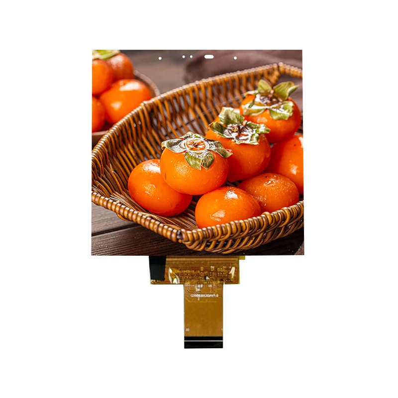
Square TFTs are becoming increasingly common in smart wearables and industrial instruments. Common specifications include 1.3-inch (240x240), 3.4-inch (480x480), and 4.0-inch (720x720).

1.3 Environmental Adaptability: Indoor, Outdoor, or Extreme Conditions?

Many projects work fine with standard screens during the prototyping phase but encounter issues once deployed in the field. Three key parameters deserve special attention:

  • Brightness: 300–400 nits is sufficient for indoor use; semi-outdoor applications require 500–800 nits; full outdoor use under direct sunlight demands 1000 nits or higher for legibility

  • Operating Temperature: Commercial grade: 0°C to 50°C; industrial grade: -20°C to 70°C; automotive or extreme environments require -30°C to 85°C or wider

  • Viewing Angle: For scenarios where multiple people view the screen or where the device is installed at an angle, IPS full-viewing-angle screens are preferred; TN screens are cheaper but exhibit significant color shift at wide angles

1.4 Touch Panel and Surface Treatment

If your product requires touch functionality, beyond choosing between resistive and capacitive types, there are several easily overlooked details:

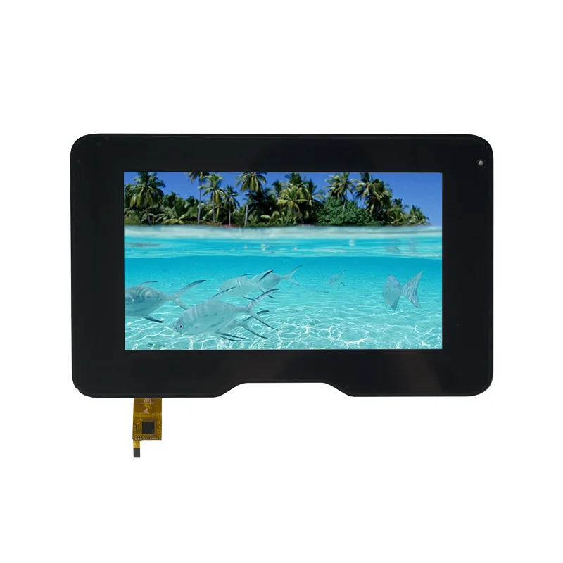
Lamination Method: Optical bonding provides better clarity and reduced reflection compared to air-gap lamination, but comes at a higher cost
Surface Coating: Anti-glare (AG), anti-reflective (AR), and anti-fingerprint (AF) coatings — for outdoor or high-brightness devices, an AG+AR combination is recommended

Cover Glass Customization: Whether rounded corners, silk-screen logos, holes, or other aesthetic modifications are required


2. Hardware and Driver: Pitfall Avoidance

Once the screen is selected, hardware design and driver development introduce another set of potential pitfalls.

2.1 FPC Cable and Connection

The FPC cable is the cause of 80% of screen glitches. Always unlock the connector latch before inserting or removing the cable — forcibly pulling it can damage the gold contacts. Never plug or unplug the FPC while the system is powered on, as residual current may burn the interface.

When customizing the FPC, pay attention to:

Whether the pin sequence and voltage levels are compatible with your mainboard
Whether bending, widening, or routing around other components is required
Whether the FPC length matches the mechanical enclosure design

2.2 Power Supply and Backlight

TFT-LCDs typically require multiple voltage rails: VDD (3.3V logic), VGH (positive bias), VGL (negative bias), and others. Abnormal power delivery is the number one cause of color distortion and screen flicker. A typical diagnostic approach is to check whether the VCOM voltage deviates from the datasheet specification (for example, exceeding 3.8V often leads to perceptible flicker).

For backlight driving, a constant-current solution with PWM dimming is recommended. If the PWM frequency drops below 150Hz, the human eye may perceive flicker; it is advisable to raise the frequency above 200Hz.

2.3 Driver IC and Graphics Library

Common TFT driver ICs include ILI9341, ST7789, and ST7735. Among these, the ILI9341 offers the most abundant documentation and the simplest driver implementation, making it suitable for 240x320 resolution applications.

For graphics libraries, LVGL and TouchGFX are the mainstream choices in the embedded space. LVGL is open-source and supports multiple platforms, while TouchGFX is deeply optimized for STM32 microcontrollers.


3. A Special Option: UART Smart Serial Screens

If your team does not want to invest significant time in graphics driver development, or if your main controller has limited resources, the UART serial screen is an option worth considering.

Such screens incorporate a built-in MCU (e.g., ATmega328PB) and can be controlled simply by sending commands over the serial port, occupying only the TX and RX pins.

UART screens on the market generally fall into two categories:

Type Development Approach Best Suited For
Smart Display Drag-and-drop GUI Builder, no coding required UI designers, rapid prototyping, teams without programming backgrounds
Entry-Level UART TFT API command control, requires basic programming Developers with programming skills who need greater control flexibility

The former offers extremely high development efficiency — you can even simulate the UI on a PC before flashing it to the screen. The latter provides more low-level control capabilities.


4. Common Fault Diagnosis Quick Reference

Finally, here is a quick-reference checklist for troubleshooting high-frequency field issues — it might just save the day:

Symptom Priority Investigation Direction
Glitched screen, no display Check if the FPC cable is loose or oxidized (80% of cases); verify resolution / refresh rate settings
Color distortion, vertical stripes, jitter Check for abnormal supply voltages (VGL/VGH/VCOM); check if PWM dimming frequency is too low
Dim image or backlight not working Check for aging backlight LEDs; verify actual output voltage of the power adapter
Fixed dark/white spots on the screen Physical damage or compression from the back side (irreversible — requires replacement)

TFT LCD selection and development is, at its core, a trade-off among cost, performance, development cycle, and reliability. There is no "best" screen — only the "most suitable" solution. I hope this guide helps you avoid unnecessary detours at the start of your project, allowing you to focus more effort on creating a truly differentiated product experience.

Related News
Leave me a message
X
We use cookies to offer you a better browsing experience, analyze site traffic and personalize content. By using this site, you agree to our use of cookies.Privacy Policy
RejectAccept